Chapter 2 Lines and Angles (Class 6 - Latest Maths NCERT (Ganita Prakash) Concept Notes)
Welcome to Chapter 2: Lines and Angles! This chapter serves as the foundation for Plane Geometry, introducing the fundamental building blocks that allow us to construct and analyze the physical world around us. We move from simple dots on a paper to the complex measurement of turns and rotations, understanding how static shapes are formed through precise mathematical rules.
The curriculum begins with the most basic geometric elements: Points, Line Segments, Lines, and Rays. We explore how a single point determines a location, while lines and rays extend our vision into infinity. A central focus of this chapter is the Concept of an Angle, which we learn to visualize as the amount of rotation or turn between two arms meeting at a Vertex. We will delve into the classification of angles—identifying Acute, Right, Obtuse, Straight, and Reflex angles—and learn the history behind the 360-degree system. Practical skills are emphasized through the use of Protractors and the construction of Angle Bisectors via paper-folding activities.
To enhance your learning, this page provides elaborate explanations, step-by-step construction guides, and real-life applications such as the geometry found in clocks, the Ashoka Chakra, and daily objects. These comprehensive resources, meticulously prepared by learningspot.co, are designed to transform abstract geometric concepts into intuitive, visual knowledge, ensuring students can identify and measure the angles that define our environment.
Basic Geometrical Ideas: Points and Lines
Geometry is the study of shapes and spaces. These ideas form the building blocks of ‘plane geometry’, which allows us to understand the construction and analysis of different figures.
Point
Imagine marking a position with a very sharp pencil tip on a paper. That mark represents a point. A point is a fundamental concept in geometry that describes a location in space. It has no size, no dimension (zero dimension), no length, no breadth, and no thickness. It simply indicates an exact position.
Points are usually represented by a tiny dot and are named using a capital letter for identification.

Examples of models of a point in real life include:
- The sharp tip of a pen or pencil.
- The corner of a table.
- The location of a city on a map.
- A star in the night sky (from our perspective).
Points help us to specify an exact location.
Line
A line is defined as a straight, one-dimensional figure that has no thickness and extends infinitely in both opposite directions. It is a fundamental concept in geometry. A line is composed of a set of infinite points that are arranged in a straight path.
Graphically, we represent a line by drawing a straight path and placing arrowheads at both ends. These arrowheads signify that the line continues endlessly in both directions.

A line can be named in two common ways:
- By using a single lowercase letter, such as line $l$, line $m$, or line $n$.
- By picking any two distinct points on the line and using their capital letters. For example, if points A and B are on the line, we can call it line AB. The notation for this is $\overleftrightarrow{AB}$ or $\overleftrightarrow{BA}$.
Since a line is infinite in length, it is impossible to draw it completely on paper. We only draw a segment of it and use arrows to indicate its infinite nature.
Important Property: An essential axiom in Euclidean geometry states that through any two distinct given points, there is exactly one unique straight line that can be drawn.
Collinear Points
When three or more points lie on the same single straight line, they are said to be collinear points. Conversely, points that do not lie on the same straight line are called non-collinear points.

In the figure shown above, points A, B, and C are collinear as they all fall on the same straight line. Point D, however, is a non-collinear point with respect to A, B, and C because it does not lie on the same line.
Note that any two points are always collinear, as per the property mentioned above, that a unique straight line can always be drawn passing through them.
Properties of Points and Lines
The following are some of the fundamental properties and axioms that describe the relationships between points, lines, and planes in Euclidean geometry. Understanding these axioms is crucial for building a foundation in geometry.
1. An infinite number of lines can pass through a single point.
Imagine a single point in space. You can draw one line passing through it. Now, you can pivot or rotate this line around that fixed point. Each new angle of rotation creates a new, distinct line. Since there are infinite possible angles for rotation, an infinite number of unique lines can be drawn through that single point.

2. Exactly one unique line can pass through two distinct points.
This is a foundational axiom of geometry. If you have two different points, say Point A and Point B, there is only one possible straight path that connects them and extends infinitely in both directions. You cannot draw a second, different straight line that also passes through both A and B. Any other path connecting them would have to be curved, and thus would not be a line.

3. If two distinct lines intersect, they intersect at exactly one point.
By definition, a line is a straight path. If two different (distinct) straight lines were to cross at more than one point, they would have to curve to meet again, which contradicts the definition of a line. Therefore, two distinct straight lines can only share one common point. If they share two or more points, they must be the exact same line.

4. The intersection of two distinct, non-parallel planes is a line.
When two flat surfaces (planes) cross each other, the location where they meet forms a straight line. A common real-world example is the corner of a room where two walls meet; their intersection is a straight line running from the floor to the ceiling. Another example is the crease formed when a piece of paper is folded; this crease is the line of intersection between the two planes formed by the folded paper.

Line Segment
A line segment is a part of a line that is bounded by two distinct endpoints. It contains these endpoints and all the points on the line between them. The primary characteristic of a line segment is that it has a fixed, measurable length.

A line segment with endpoints A and B is denoted as $\overline{AB}$ or $\overline{BA}$. The order of the endpoints does not matter when naming a line segment. The length of the line segment $\overline{AB}$ is denoted simply as AB.
Examples of models representing line segments in real life include:
- The edge of a table or a book.
- A pencil or a ruler.
- A stretched piece of thread between two points.
Ray
A ray is also a part of a line. It has one fixed endpoint (called the initial point or origin) and extends infinitely in one direction from that point.

A ray is named using its endpoint first, followed by any other point on the ray. For example, a ray starting at endpoint A and passing through point B is denoted as $\overrightarrow{AB}$. The order of the letters is crucial:
- The first letter must be the endpoint.
- The second letter indicates the direction of the infinite extension.
Therefore, $\overrightarrow{AB}$ and $\overrightarrow{BA}$ are two different rays. $\overrightarrow{BA}$ would start at B and extend infinitely through A.
Since a ray extends infinitely in one direction, it does not have a measurable length.
Examples of models of rays in real life:
- A ray of light from the sun or a flashlight.
- The beam from a laser pointer.
Opposite Rays
Two rays are called opposite rays if they share the same endpoint and form a straight line. For three collinear points A, O, and B, if O is between A and B, then $\overrightarrow{OA}$ and $\overrightarrow{OB}$ are opposite rays.

The union of two opposite rays is a line.
Comparing Line, Line Segment, and Ray
The following table summarizes the key differences between a line, a line segment, and a ray:
| Feature | Line | Line Segment | Ray |
|---|---|---|---|
| Endpoints | Zero endpoints | Two endpoints | One endpoint (initial point) |
| Extension | Extends infinitely in both directions | Does not extend; has a fixed position | Extends infinitely in one direction |
| Length | Infinite (cannot be measured) | Finite and definite (can be measured) | Infinite (cannot be measured) |
| Notation Symbol | $\overleftrightarrow{AB}$ | $\overline{AB}$ or $\overline{BA}$ | $\overrightarrow{AB}$ (starting point first) |
| Diagram |  |
 |
 |
Angles: Concepts and Representation
In the study of geometry, understanding how basic elements like points and lines combine to form complex shapes is essential. This section covers the core components of angles, the concept of rotation, and the structural formation of triangles and quadrilaterals.
Components of an Angle
In the study of geometry, an angle is not merely a static shape but a representation of the relationship between two rays. To understand this relationship, we must break down the angle into its fundamental structural elements: the Vertex and the Arms.
Vertex
The Vertex is the singular, precise location where the geometric construction of an angle begins. It serves as the originating point for the two rays that define the angle's spread.
- It acts as the pivot point for rotation when measuring the size of the angle.
- In any closed polygon, such as a triangle or a quadrilateral, the vertices are the "corners" where the sides meet.
$\text{Vertex} = \text{Point } B$
[Origin of rays]
Arms
The Arms of an angle are the two rays that extend infinitely from the vertex. While in practical drawings we see them as line segments, mathematically they are rays because they have a fixed starting point but no end point.
1. Initial Arm: The ray that serves as the starting position for measuring rotation (usually the horizontal ray).
2. Terminal Arm: The ray that represents the final position after the rotation or "turn" has occurred.
If $A$ and $C$ are points on the respective rays originating from $B$, the arms are denoted using the ray symbol:
$\text{Arms} = \{ \overrightarrow{BA}, \overrightarrow{BC} \}$
Naming Logic and Notation: The Middle Letter Rule
The naming of an angle follows a strict logical sequence to ensure that the Vertex is uniquely identified. The standard convention uses three capital letters.
When writing the name of an angle, the letter representing the vertex must always be placed in the middle. This signifies that the path of the angle goes from one point on an arm, through the vertex, to a point on the other arm.
$\angle ABC \text{ or } \angle CBA$
(Correct: Vertex $B$ is middle)
$\angle BAC \text{ or } \angle BCA$
(Incorrect: Vertex is not $A$ or $C$)
Size of an Angle as a Measure of Rotation
The magnitude or size of an angle is a measure of the circular spread between its two arms. A common misconception in geometry is that the size of an angle depends on the length of the rays (arms) drawn on paper. However, the size is strictly defined by the amount of rotation performed to move from the initial arm to the terminal arm.
The Concept of Angular Rotation
Imagine one arm of an angle is fixed (Initial Arm) and the other is free to rotate around the vertex. The further you rotate the free arm, the larger the angle becomes. This is distinct from linear distance; it is a rotational turn.
Misconception: Length vs. Angle
If you extend the lines of an angle, the angle does not increase. The angle remains the same because the "opening" or the "turn" between the lines has not changed. This is why we use a circle as the basis for measurement, as every point on a circle is equidistant from the center (the vertex).
The Degree System ($\text{Sexagesimal System}$)
To measure rotation precisely, mathematicians established a standard unit called the Degree. This system is based on dividing one complete, full rotation into $360$ equal parts.
Definition of $1$ Degree ($1^\circ$)
If a full rotation is divided into $360$ equal slices, the measure of one such slice is defined as one degree ($1^\circ$).
$\text{Full Rotation} = 360^\circ$
[Standard Definition]
Why the number 360?
The choice of $360$ is mathematically significant because it is a highly composite number. It can be divided evenly by $2, 3, 4, 5, 6, 8, 9, 10, 12, 15, 18, 20, 24, 30, 36, 40, 45, 60, 72, 90, 120,$ and $180$. This makes it extremely easy to calculate fractions of a turn (like half, quarter, or third) without dealing with decimals.
The Wheel of Time
The number $360$ has deep astronomical and cultural roots. Ancient Indian mathematicians observed the solar year to be approximately $360$ days.
The Rigveda (one of the oldest known texts) contains a verse describing the "Wheel of Time":
"Twelve spokes, one wheel, navels three. Who can comprehend this? On it are placed together three hundred and sixty like spokes." ($\text{Rigveda } 1.164.48$)
This "Wheel" represents the year, and the $360$ spokes represent the days/degrees of the circular path of time. This signifies that the concept of dividing a circle into $360$ parts is an ancient tradition in India used to track the movement of the sun and stars.
Standard Angle Measures
Using the full rotation of $360^\circ$ as a base, we can derive the measures of other fundamental angles by calculating the fractions of a complete turn.
Straight Angle
A straight angle is formed when the rotation is exactly half of a full turn. The arms lie in a straight line extending in opposite directions from the vertex.
$\text{Straight Angle} = \frac{1}{2} \times \text{Full Rotation}$
$\text{Straight Angle} = \frac{1}{2} \times 360^\circ$
$\text{Straight Angle} = 180^\circ$
[Half-turn measure]
Right Angle
A right angle is formed when the rotation is exactly one-fourth (a quarter) of a full turn, or half of a straight angle.
$\text{Right Angle} = \frac{1}{4} \times \text{Full Rotation}$
$\text{Right Angle} = \frac{1}{4} \times 360^\circ$
$\text{Right Angle} = 90^\circ$
[Quarter-turn measure]
Rotation vs. Degrees
The following table illustrates the relationship between the amount of turn and its corresponding degree measure.
| Fraction of Turn | Calculation | Degree Measure |
|---|---|---|
| Full Turn | $1 \times 360^\circ$ | $360^\circ$ |
| Three-Quarter Turn | $\frac{3}{4} \times 360^\circ$ | $270^\circ$ |
| Half Turn (Straight) | $\frac{1}{2} \times 360^\circ$ | $180^\circ$ |
| Quarter Turn (Right) | $\frac{1}{4} \times 360^\circ$ | $90^\circ$ |
| One-Sixth Turn | $\frac{1}{6} \times 360^\circ$ | $60^\circ$ |
| One-Twelfth Turn | $\frac{1}{12} \times 360^\circ$ | $30^\circ$ |
Formation of a Triangle
A Triangle is the simplest polygon, formed by connecting three non-collinear points (points not lying on the same straight line).
To Form: Take three points $A, B,$ and $C$. Join them using three line segments $AB, BC,$ and $CA$.
Angle Sum Property of a Triangle
One of the most important properties of a triangle is that the sum of its three interior angles is always $180^\circ$.
$\angle A + \angle B + \angle C = 180^\circ$
Formation of a Quadrilateral
A Quadrilateral is a four-sided polygon formed by connecting four points, where no three points are collinear.
To Form: Take four points $P, Q, R,$ and $S$. Join them in order to form line segments $PQ, QR, RS,$ and $SP$.
Angle Sum Property of a Quadrilateral
The sum of the interior angles of any quadrilateral is $360^\circ$.
A quadrilateral can be divided into two triangles by drawing a diagonal.
1. Sum of angles in Triangle 1 $= 180^\circ$
2. Sum of angles in Triangle 2 $= 180^\circ$
3. Total Sum $= 180^\circ + 180^\circ = 360^\circ$
$\text{Sum of Interior Angles} = 360^\circ$
Comparing Angles: Without Using Protractor
Comparing angles involves determining which angle has a larger amount of rotation or "spread" between its arms. While we can estimate the size of an angle by looking at it, geometric precision requires specific methods to compare two angles accurately without necessarily knowing their exact degree measures.
Method of Superimposition
Superimposition is the most direct way to compare two angles. It involves physically or mentally placing one angle directly on top of the other to observe the difference in their openings.
Steps for Superimposition:
1. Identify the two angles to be compared, say $\angle ABC$ and $\angle PQR$.
2. Place the vertex of the second angle ($Q$) exactly over the vertex of the first angle ($B$). This point is the pivot of our comparison.
3. Align one arm of the second angle (say $QR$) along one arm of the first angle (say $BC$). Ensure that both angles are facing the same direction.
Logic of Comparison
Once the vertices and one arm are perfectly aligned, the relative position of the second arm ($QP$ relative to $BA$) determines the result of the comparison. There are three possible outcomes:
Case I: Smaller Angle
If arm $QP$ falls inside the opening of $\angle ABC$, it implies that $\angle PQR$ requires less rotation than $\angle ABC$.
$\angle PQR < \angle ABC$
Case II: Larger Angle
If arm $QP$ falls outside the opening of $\angle ABC$, it implies that $\angle PQR$ requires more rotation than $\angle ABC$.
$\angle PQR > \angle ABC$
Case III: Equal Angles
If arm $QP$ falls exactly on arm $BA$, then the two angles represent the exact same amount of rotation.
$\angle PQR = \angle ABC$
[When arms overlap perfectly]
Comparison using a Circular Tool (Transparent Circle)
A highly effective and more technical way to compare angles without using a standard protractor is by using a transparent circular sheet. This method serves as a bridge between simple visual comparison and formal degree measurement.
The Circle as a Gauge
In geometry, a circle is a set of all points equidistant from a fixed center. When we place the center of a circle on the vertex of an angle, the distance between the two arms along the edge of the circle (the arc) directly represents the magnitude of that angle.
Why use a circle?
Using a circular tool ensures that we are measuring the "turn" at a consistent distance from the vertex. This eliminates the confusion caused by different arm lengths and focuses solely on the rotational spread.
The Procedure for Comparison
To compare two angles, say $\angle ABC$ and $\angle XYZ$, follow these steps:
Step 1: Calibration on the First Angle
Place the center of the transparent circular sheet exactly on the vertex $B$ of $\angle ABC$. Using a marker, make a dot ($P_1$) where arm $BC$ intersects the circle's edge, and another dot ($P_2$) where arm $BA$ intersects it.
Step 2: Transfer and Alignment
Move the circular sheet to the second angle, $\angle XYZ$. Place the center of the circle on vertex $Y$. Rotate the sheet so that the first mark ($P_1$) lies exactly on the arm $YZ$.
Step 3: Evaluation of the Second Arm
Now, observe the position of the second arm ($YX$) relative to the second mark ($P_2$) on the circle.
Interpreting the Results
Based on the relative position of the arm $YX$ and the mark $P_2$, we can conclude the comparison as follows:
| Observation of Arm $YX$ | Comparison Result | Mathematical Conclusion |
|---|---|---|
| Passes Short of mark $P_2$ | $\angle XYZ$ is smaller | $\angle XYZ < \angle ABC$ |
| Passes Beyond mark $P_2$ | $\angle XYZ$ is larger | $\angle XYZ > \angle ABC$ |
| Passes Exactly through $P_2$ | Angles are equal | $\angle XYZ = \angle ABC$ |
Measuring Angles and the Protractor
To go beyond simple comparison, we need a way to quantify the size of an angle using numbers. This process is called measurement. The standard tool for this purpose is the Protractor, and the unit of measurement is the Degree ($^\circ$).
Understanding the Protractor
A standard protractor is a semi-circular tool marked from $0$ to $180$. It has several key features that must be understood before use:
- Center Point: The hole or mark at the center of the straight edge. This must be placed on the vertex of the angle.
- Baseline (0-line): The straight line passing through the center point to the $0^\circ$ marks.
- Inner Scale: Reads from $0^\circ$ to $180^\circ$ in a clockwise direction (usually starting from the right).
- Outer Scale: Reads from $0^\circ$ to $180^\circ$ in an anti-clockwise direction (usually starting from the left).
How to Measure an Angle
To measure an angle, such as $\angle ABC$, follow these systematic steps:
Step 1: Alignment of Vertex
Place the Center Point of the protractor exactly on the vertex ($B$) of the angle.
Step 2: Alignment of Baseline
Rotate the protractor (while keeping the center on the vertex) so that the Baseline falls exactly on one arm of the angle, say arm $BC$. Ensure this arm points toward the $0^\circ$ mark.
Step 3: Choosing the Scale
Identify which scale (Inner or Outer) has the $0^\circ$ mark on the arm $BC$. Use only that scale to read the measurement.
Step 4: Reading the Value
Follow that scale to the point where the second arm ($BA$) crosses the edge of the protractor. This number is the measure of the angle in degrees.
$m\angle ABC = 60^\circ$
[Measure of the angle]
Common Mistakes to Avoid (Mind the Mistake)
Many students make errors while measuring angles. Being aware of these can improve accuracy.
A. Incorrect Vertex Placement
Mistake: Placing the bottom edge of the plastic protractor on the vertex instead of the actual Center Point mark.
Correction: Always ensure the vertex point is visible through the center hole or aligned with the crosshair.
B. Wrong Scale Selection
Mistake: Reading $150^\circ$ instead of $30^\circ$ because the wrong scale (Inner vs Outer) was used.
Correction: Always start counting from zero on the arm that is aligned with the baseline. If an angle looks acute (sharp), its measure must be less than $90^\circ$.
C. Misalignment of the Baseline
Mistake: The baseline is slightly above or below the arm of the angle.
Correction: The arm of the angle should be perfectly "hidden" under the $0^\circ$ line of the protractor.
Types of Angles and Classification
Angles are categorized into specific groups based on their degree measures. This classification helps in describing the relationship between lines and the orientation of various geometric shapes.
Classification of Angles
The size of an angle is measured between $0^\circ$ and $360^\circ$. Depending on where the measure falls, we use different names to identify them.
| Type of Angle | Description | Measure | Figure |
|---|---|---|---|
| Zero Angle | The two arms of the angle overlap completely. There is no rotation. | $0^\circ$ | 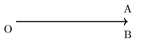 |
| Acute Angle | An angle that is smaller than a right angle. | Greater than $0^\circ$ and less than $90^\circ$ | 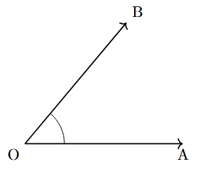 |
| Right Angle | An angle that forms a perfect corner, like that of a square. It is one-quarter of a full turn. | Exactly $90^\circ$ | 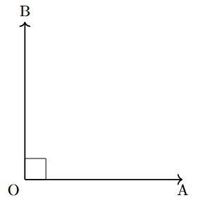 |
| Obtuse Angle | An angle that is larger than a right angle but smaller than a straight angle. | Greater than $90^\circ$ and less than $180^\circ$ | 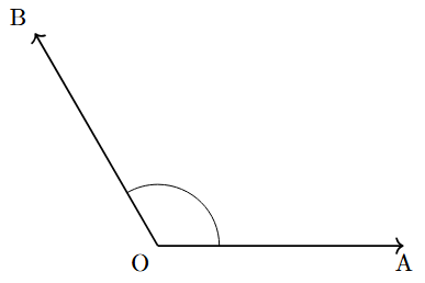 |
| Straight Angle | An angle that forms a straight line. It is one-half of a full turn. | Exactly $180^\circ$ | 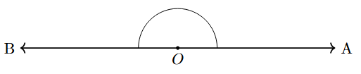 |
| Reflex Angle | An angle that is larger than a straight angle but smaller than a complete angle. It represents the larger turn between two arms. | Greater than $180^\circ$ and less than $360^\circ$ | 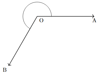 |
| Complete Angle | An angle where one arm has made a full rotation to return to its starting position. | Exactly $360^\circ$ | 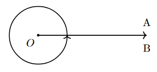 |
Perpendicular Lines
Two lines are said to be perpendicular when they meet or intersect at an angle of exactly $90^\circ$. This specific intersection forms four right angles around the point of intersection.
If we consider two lines $l$ and $m$, they are perpendicular if the rotation required to move from $l$ to $m$ is a quarter turn ($90^\circ$). The mathematical symbol for perpendicularity is $\perp$.
$l \perp m$
[Read as "$l$ is perpendicular to $m$"]

Angle Bisectors
An Angle Bisector is a ray that originates from the vertex of an angle and divides it into two congruent (equal) smaller angles. The bisector represents the axis of symmetry for the angle.
Mathematical Relationship and Property
If a ray $OC$ is the angle bisector of $\angle AOB$, then every point on the ray $OC$ is equidistant from the arms $OA$ and $OB$. The total measure of the angle is halved.
$\angle AOC = \angle COB$
(By Definition of Bisector)
$m\angle AOC = \frac{1}{2} \times m\angle AOB$
Construction by Paper Folding (The Practical Approach)
Paper folding is a powerful visual method to verify the existence of a bisector. This method relies on superimposition.
- Step 1: Draw an angle $\angle AOB$ on a translucent sheet of paper.
- Step 2: Fold the paper such that the arm $OA$ is placed exactly over the arm $OB$, ensuring the fold passes through the vertex $O$.
- Step 3: Press the paper to create a sharp crease and then unfold it.
The resulting crease is the Angle Bisector because it creates two perfectly matching halves through the act of folding.