
Top
Learning Spot
Menu

Chapter 4 Exploring Some Geometric Themes (Class 8 - Latest Maths NCERT (Ganita Prakash II) Solutions)

Looking for precise and illustrative NCERT Solutions for Chapter 4: Exploring Some Geometric Themes? You’ve come to the right place! This page offers comprehensive, step-by-step answers for the latest Class 8 Maths curriculum, guiding you through the mesmerizing world of Fractals. We provide detailed explanations for the self-similar patterns found in the Sierpinski Carpet and the Koch Snowflake, helping you understand how simple mathematical rules create the infinite complexity seen in nature and the Kandariya Mahadev Temple.

Our solutions focus on sharpening your spatial reasoning through the Visualising Solids section. We offer clear guides on identifying the front, top, and side profiles of 3D objects and provide accurate diagrams for Nets of various solids, including all 11 ways to unfold a cube. You will also find logical walkthroughs for the "Shortest Path" problem, where we use flat nets to find the most efficient route for an ant on a 3D surface, turning a challenging puzzle into a simple geometric exercise.

In the final section, we help you master Projections and Isometric Drawings. Our solutions provide clear tutorials on using isometric grids to represent depth and height on a 2D plane, including a breakdown of geometric illusions like the "Impossible Triangle." These resources, curated by learningspot.co based on the Ganita Prakash II textbook, provide step-by-step fractal generation guides, visual net animations, and drawing tips to ensure you excel in your Class 8 geometry assessments.

Content On This Page
Figure It Out (Page No. 72) Figure It Out (Page No. 73) Figure It Out (Page No. 80 - 81)
Figure It Out (Page No. 92 - 93) Figure It Out (Page No. 95 - 97) Figure It Out (Page No. 100 - 102)


Figure It Out (Page No. 72)

Question 1. Draw the initial few steps (at least till Step $2$) of the shape sequence that leads to the Sierpinski Triangle.

Answer:

Construction:

The Sierpinski Triangle is a fractal constructed through a process of recursive subtraction. In the Indian context, similar recursive geometric patterns can be found in Kolam art and the intricate stone carvings of Hoysala temples.


Step 0: We start with a solid equilateral triangle.

Step 1: Connect the midpoints of the three sides. This divides the triangle into four smaller, identical equilateral triangles. We remove the central triangle (creating a 'hole'). There are now 3 solid triangles remaining.

Step 2: For each of the 3 remaining solid triangles from Step 1, we repeat the process: connect their midpoints and remove the central part. There are now $3 \times 3 = 9$ smaller solid triangles remaining.


A diagram showing three stages of the Sierpinski Triangle: a solid triangle, a triangle with one central hole, and a triangle with multiple smaller holes.

Question 2. Find the number of holes, and the triangles that remain at each step of the shape sequence that leads to the Sierpinski Triangle.

Answer:

Solution:

By observing the construction process, we can determine the progression of solid triangles and holes at each stage.


Step ($n$) Remaining Triangles New Holes Added Total Holes
0$3^0 = 1$00
1$3^1 = 3$11
2$3^2 = 9$34
3$3^3 = 27$913

General Formula:

1. The number of remaining triangles at Step $n$ is given by $3^n$.

2. The total number of holes ($H_n$) follows the formula: $H_n = \frac{3^n - 1}{2}$.


Indian Perspective:

This exponential growth in the number of shapes is a classic example of Geometric Progression (Gunottara Shreni), which was studied extensively by ancient Indian mathematicians like Pingala and Mahavira in the context of combinatorics and prosody.

Question 3. Find the area of the region remaining at the $n$th step in each of the shape sequences that lead to the Sierpinski fractals. Take the area of the starting square/triangle to be $1$ sq. unit.

Answer:

To Find:

The remaining area at Step $n$ for both the Sierpinski Triangle and the Sierpinski Carpet (Square).


1. Sierpinski Triangle:

At each step, we divide the existing solid area into 4 parts and remove 1 part. This means we keep three-fourths ($3/4$) of the area from the previous step.

Step 0: Area $= 1$

Step 1: Area $= 1 \times \frac{3}{4} = \frac{3}{4}$

Step 2: Area $= \frac{3}{4} \times \frac{3}{4} = \left(\frac{3}{4}\right)^2$

$\text{Area}_n = \left(\frac{3}{4}\right)^n$

[For the Triangle]


2. Sierpinski Carpet (Square):

In this fractal, a square is divided into 9 smaller squares, and the central one is removed. This means we keep eight-ninths ($8/9$) of the area at each step.

Step 0: Area $= 1$

Step 1: Area $= 1 \times \frac{8}{9} = \frac{8}{9}$

Step 2: Area $= \frac{8}{9} \times \frac{8}{9} = \left(\frac{8}{9}\right)^2$

$\text{Area}_n = \left(\frac{8}{9}\right)^n$

[For the Carpet/Square]


Conclusion:

As $n$ approaches infinity, the remaining area for both fractals approaches Zero. This paradoxical result—where a shape has a defined perimeter but no area—is a key concept in modern fractal geometry, often related to the concept of Ananta (Infinity) in Indian philosophy.


Figure It Out (Page No. 73)

Question 1. Draw the initial few steps (at least till Step $2$) of the shape sequence that leads to the Koch Snowflake.

Answer:

Construction:

The Koch Snowflake is a fractal curve constructed by repeatedly modifying each line segment of an equilateral triangle. In the Indian artistic tradition, such self-similar patterns are often seen in Mandala designs and temple ceilings, representing the concept of the cosmos repeating at every scale.


Step 0 (The Initiator): Start with a single equilateral triangle.

Step 1: Divide each side into three equal segments. Replace the middle segment of each side with two sides of a smaller equilateral triangle pointing outwards. This results in a six-pointed star (like the Shatkona symbol used in Indian culture).

Step 2: Repeat the process for each of the $12$ smaller segments created in Step 1. Each straight segment is again broken into four smaller parts with a triangular "bump" in the middle.


A diagram showing the progression of the Koch Snowflake from an equilateral triangle to a six-pointed star and then a more jagged snowflake shape.

Question 2. Find the number of sides in the $n$th step of the shape sequence that leads to the Koch Snowflake.

Answer:

Given:

At each step of the Koch Snowflake construction, every single line segment is replaced by 4 smaller segments.


To Find:

The total number of sides at Step $n$.


Solution:

Let $N_n$ be the number of sides at step $n$.

1. At Step $0$: The shape is a triangle, so $N_0 = 3$.

2. At Step $1$: Each of the $3$ sides is replaced by $4$ new sides. So, $N_1 = 3 \times 4 = 12$.

3. At Step $2$: Each of the $12$ sides is replaced by $4$ new sides. So, $N_2 = 12 \times 4 = 48$.


General Observation:

We can see that the number of sides follows a Geometric Progression (Gunottara Shreni):

Step ($n$) Calculation Number of Sides ($N_n$)
0$3 \times 4^0$3
1$3 \times 4^1$12
2$3 \times 4^2$48
3$3 \times 4^3$192

Conclusion:

The general formula for the number of sides at the $n$th step is $N_n = 3 \times 4^n$.

Question 3. Find the perimeter of the shape at the $n$th step of the sequence. Take the starting equilateral triangle to have a sidelength of $1$ unit.

Answer:

Given:

Initial side length at Step $0$ is $s_0 = 1$ unit.


To Find:

The total perimeter ($P_n$) of the shape at Step $n$.


Solution:

In each step, the length of each individual segment becomes one-third ($\frac{1}{3}$) of its previous length.

1. At Step $0$: Side length $= 1$. Number of sides $= 3$. Perimeter $P_0 = 3 \times 1 = 3$.

2. At Step $1$: Side length $= \frac{1}{3}$. Number of sides $= 12$. Perimeter $P_1 = 12 \times \frac{1}{3} = 4$.

3. At Step $2$: Side length $= \frac{1}{9}$. Number of sides $= 48$. Perimeter $P_2 = 48 \times \frac{1}{9} = \frac{16}{3} \approx 5.33$.


Mathematical Logic:

In each step, the total number of sides increases by a factor of 4, while the length of each side decreases by a factor of 3. Thus, the perimeter increases by a factor of $\frac{4}{3}$ at every step.

$P_n = P_0 \times \left(\frac{4}{3}\right)^n$

$P_n = 3 \times \left(\frac{4}{3}\right)^n$

... (i)


Indian Perspective:

As the number of steps ($n$) becomes very large (approaching Ananta or Infinity), the perimeter $P_n$ continues to grow without bound. This is a mathematical paradox from the Indian perspective of infinity: a shape that can fit inside a small $\textsf{₹} 10$ coin (finite area) but has a boundary of infinite length.


Figure It Out (Page No. 80 - 81)

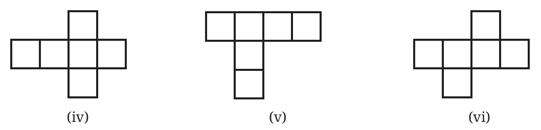
Question 1. Which of the following are the nets of a cube? First, try to answer by visualisation. Then, you may use cutouts and try.
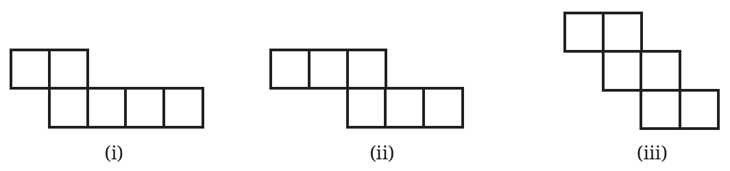
Net diagrams to identify as potential cube nets (i) to (iii)
Six different net diagrams to identify as potential cube nets (iv) to (vi)

Answer:

Solution:

To determine if a two-dimensional arrangement of six squares is a net of a cube, we must ensure that when folded, every face meets an edge without overlapping and forms a closed 3D shape. In the Indian school curriculum, students are taught to look for specific patterns like the $1-4-1$ or $2-3-1$ configurations.


Evaluation of Nets:

1. (ii), (iii), (iv), (vi): These are valid nets. When folded, they will form a perfect cube.

2. (i): This is not a net because two squares will overlap, leaving one side of the cube open.

3. (v): This is not a net because the squares are arranged such that they cannot wrap around to form all six faces.

4. Last Image (Bottom row): All three diagrams shown in the bottom row of the second image are valid nets of a cube.


Indian Perspective:

Understanding nets is very useful in India for industries like packaging. Whether it is a box for Indian sweets (Mithai) or a cardboard carton for shipping goods, designers first create these 2D nets before folding them into the 3D boxes we see in shops.

Question 2. A cube has $11$ possible net structures in total. In this count, two nets are considered the same if one can be obtained from the other by a rotation or a flip. For example, the following nets are all considered the same —
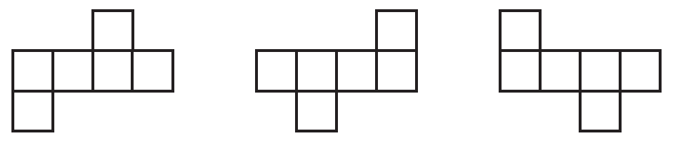
Examples of cube nets that are identical through rotation or flipping

Find all the $11$ nets of a cube.

Answer:

Solution:

There are exactly $11$ unique ways to unfold a cube. These can be grouped into four categories based on the number of squares in the longest central row.


1. Group 1-4-1 (6 Nets):

These have a central row of $4$ squares with $1$ square on either side. These look like variants of a "Cross" or the letter "T".

2. Group 2-3-1 (3 Nets):

These have a central row of $3$ squares, with $2$ squares attached to one side and $1$ to the other in various positions.

3. Group 2-2-2 (1 Net):

This is the "Staircase" net where pairs of squares are offset from each other.

4. Group 3-3 (1 Net):

This consists of two rows of $3$ squares attached together but offset by one position.


A chart displaying all 11 unique nets of a cube grouped by their row structure.

Note: Any other configuration you find will simply be a rotation (turning it around) or a reflection (flipping it over) of one of these $11$ fundamental shapes.

Question 3. Draw a net of a cuboid having sidelengths:

(i) $5$ cm, $3$ cm, and $1$ cm

(ii) $6$ cm, $3$ cm, and $2$ cm

Answer:

Solution:

A cuboid net consists of $6$ rectangular faces. These faces come in $3$ pairs of identical rectangles. To draw a valid net, we arrange these pairs so they fold into a closed box. The most common arrangement is the $1-4-1$ layout.


(i) For Dimensions $5$ cm, $3$ cm, and $1$ cm:

The pairs of faces are:

1. Two faces of $5 \times 3 \text{ cm}^2$ (Top and Bottom)

2. Two faces of $5 \times 1 \text{ cm}^2$ (Front and Back)

3. Two faces of $3 \times 1 \text{ cm}^2$ (Left and Right Sides)

Net of a 5x3x1 cuboid showing the arrangement of the six rectangular faces

(ii) For Dimensions $6$ cm, $3$ cm, and $2$ cm:

The pairs of faces are:

1. Two faces of $6 \times 3 \text{ cm}^2$

2. Two faces of $6 \times 2 \text{ cm}^2$

3. Two faces of $3 \times 2 \text{ cm}^2$

Net of a 6x3x2 cuboid showing the arrangement of the six rectangular faces

Indian Perspective:

In many Indian households, empty matchboxes or toothpaste boxes (which are cuboids) are used by children to learn geometry. If you carefully unglue the edges of a Colgate or Pepsodent box and flatten it out, you will see a net very similar to the ones described above. This is an excellent way to practice spatial reasoning.


Figure It Out (Page No. 92 - 93)

Question 1. Observe the front view, top view and side view of the different lines in Fig. 4.6. Is there any relation between their lengths?
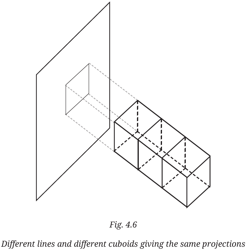
Fig 4.6 showing front, top, and side views of different lines

Answer:

Given:

Figure 4.6 shows three different cuboids of different lengths (depths). All these cuboids are projected onto a single vertical plane, creating a common front view.


To Find:

The relation between the lengths of the lines in the front view, top view, and side view.


Solution:

By observing the given figure, we can derive the following points regarding the lengths of the lines (edges) in different views:

1. Front View: In the front view, all three cuboids appear as the same square. This is because the lines representing the depth (length) of the cuboids are perpendicular to the plane of projection. Therefore, their projected length in the front view is $0$.

2. Top View: If we look from the top, we see the width and the actual depth of each cuboid. Since the cuboids have different depths, the lengths of the lines in the top view will be different and will correspond to their actual lengths.

3. Side View: Similarly, in the side view, we see the height and the actual depth. The horizontal lines in the side view will represent the actual length of each different cuboid.

Therefore, for the lines representing the depth of the cuboids:

$\text{Length in Front View} = 0$

$\text{Length in Top View} = \text{Actual Length of the line}$


Conclusion:

There is no relation between the lengths of the lines in the front view and their actual lengths when the lines are perpendicular to the plane. However, the lengths in the top view and side view are equal to each other as they both represent the actual depth of the cuboid.

$\text{Length in Top View} = \text{Length in Side View}$

Question 2. Find the front view, top view and side view of each of the following solids, fixing its orientation with respect to the vertical, horizontal and side planes: cube, cuboid, parallelepiped, cylinder, cone, prism, and pyramid. If needed, see the next problem for clues.

Answer:

Given:

A list of 3D solids: Cube, Cuboid, Parallelepiped, Cylinder, Cone, Prism, and Pyramid.


To Find:

The Front View, Top View, and Side View of each solid by fixing its orientation with respect to the horizontal and vertical planes.


Solution:

To find the views, we assume the solids are placed in a standard orientation (usually resting on their base on the horizontal plane). In the Indian perspective of Orthographic Projections, these views represent the 2D shapes seen from different directions.

Solid Name Front View Top View Side View
Cube Square Square Square
Cuboid Rectangle Rectangle Rectangle
Parallelepiped Parallelogram Rectangle / Parallelogram Parallelogram
Cylinder (Standing) Rectangle Circle Rectangle
Cone (Standing) Triangle Circle with a point at center Triangle
Triangular Prism Rectangle Triangle Rectangle
Square Pyramid Triangle Square with diagonals Triangle

Detailed Observations:

1. Cylinder: When a cylinder is placed vertically on its circular base, the front and side views are identical rectangles of height $h$ and width equal to the diameter $2r$. The top view is a circle of radius $r$.

2. Cone: The top view of a cone is a circle, but it includes a small dot in the center which represents the Apex (vertex) of the cone seen from above.

3. Pyramid: For a square pyramid, the top view shows a square. The lines connecting the corners to the center (diagonals) represent the slant edges meeting at the top vertex.

4. Parallelepiped: Since its faces are parallelograms, its projections onto vertical planes appear as parallelograms unless it is a rectangular parallelepiped (cuboid).


Final Conclusion:

The views of a solid depend on how it is oriented. In general, views are 2D shapes that help us understand the 3D structure. For most symmetric solids like the cube and standing cylinder, at least two of the three views are often identical.

Question 3. Match each of the following objects with its projections.
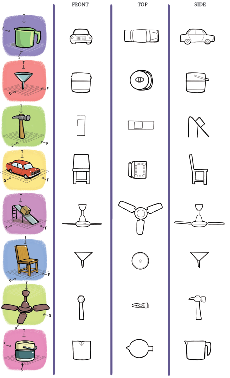
Grid showing various objects and their corresponding front, top, and side projections

Answer:

Given:

An image containing a list of 8 3D objects on the left and their jumbled Front, Top, and Side projections in a grid format.


To Find:

Matching each object with its correct set of projections.


Solution:

By observing the geometry of each object and imagining looking at it from the directions indicated by the arrows (F for Front, T for Top, and S for Side), we can identify the corresponding 2D shapes.

1. Mug (Green): When viewed from the front, it looks like a bucket shape. From the top, it is a circle with a small handle extension. From the side, the full handle is visible. This matches the 8th row of projections.

2. Funnel (Blue): The front and side views are triangular with a spout. The top view is a circle with a small circle in the middle. This matches the 6th row of projections.

3. Hammer: The side view shows the "claw" profile. The top view shows the rectangular head and the length of the handle. The front view shows the circular face of the hammer head. This matches the 7th row of projections.

4. Car (Red): The front view shows the headlights and grille. The top view shows the roof, bonnet, and boot. The side view shows the doors and wheels. This matches the 1st row of projections.

5. Slide: The side view shows the ladder and the slope. The top view shows the rectangular width and the box at the top. The front view shows the ladder frame. This matches the 3rd row of projections.

6. Chair: The front view shows the legs and the backrest. The top view shows the square seat. The side view shows the profile of the seat and backrest. This matches the 4th row of projections.

7. Ceiling Fan: The top view clearly shows the three blades. The front and side views show the central motor and the edge of the blades. This matches the 5th row of projections.

8. Tiffin Box: The front and side views show the cylindrical body and the handle lid. The top view shows the circular lid and the carrying handle. This matches the 2nd row of projections.


Final Matching Table:

Object (Left Column) Matching Projections (Row Number)
1. Mug (Green) Row 8
2. Funnel (Blue) Row 6
3. Hammer Row 7
4. Car (Red) Row 1
5. Slide Row 3
6. Chair Row 4
7. Ceiling Fan Row 5
8. Tiffin Box Row 2

Note: In Class 8 Geometry, this exercise helps in developing spatial visualization skills, which are essential for engineering drawing and understanding 3D objects in everyday life from an Indian perspective (like identifying a car or a tiffin box from different angles).


Figure It Out (Page No. 95 - 97)

Question 1. Draw the top view, front view and the side view of each of the following combinations of identical cubes.
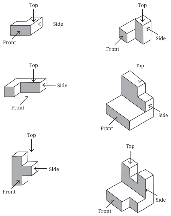
Various 3D arrangements of identical cubes with Front, Top, and Side labels

Answer:

Given:

Six different combinations of identical cubes with specific directions marked for Front, Top, and Side views.


To Find:

The 2D shapes representing the Top View, Front View, and Side View of each combination.


Solution:

In orthographic projections, we represent a 3D object by drawing it as seen from three mutually perpendicular directions. For these cube combinations, each view will consist of a set of squares.

Let us analyze each solid one by one (from top-left to bottom-right):

1. First Solid (Top-Left):

Front View: It shows three squares arranged horizontally in a single row.

Top View: It shows three squares forming an "L" shape.

Side View: It shows two squares arranged horizontally.


2. Second Solid (Top-Right):

Front View: It shows three squares in an "L" shape (two vertical on the right, one attached at the bottom left).

Top View: It shows two squares arranged vertically.

Side View: It shows two squares arranged vertically.


3. Third Solid (Middle-Left):

Front View: It shows three squares in an "L" shape (two horizontal at the bottom, one on top of the left square).

Top View: It shows three squares arranged in a single horizontal row.

Side View: It shows two squares arranged vertically.


4. Fourth Solid (Middle-Right):

Front View: It shows a base of two squares with one square placed on top of the right square.

Top View: It shows four squares arranged in a $2 \times 2$ grid.

Side View: It shows a base of two squares with one square placed on top of the left square.


5. Fifth Solid (Bottom-Left):

Front View: It shows four squares in a "T" shape (three squares in a vertical column and one square attached to the middle-right).

Top View: It shows two squares arranged horizontally.

Side View: It shows three squares arranged in a single vertical column.


6. Sixth Solid (Bottom-Right):

Front View: It shows three squares at the base with two squares on top of the outer ones, forming a "U" shape (total 5 squares visible).

Top View: It shows five squares arranged in a "U" shape.

Side View: It shows three squares at the base with one additional square on top of the right-most square (total 4 squares visible).


Summary Table:

Solid Front View (Squares) Top View (Squares) Side View (Squares)
Solid 1 3 in a row L-shape (3) 2 in a row
Solid 2 L-shape (3) 2 in a column 2 in a column
Solid 3 L-shape (3) 3 in a row 2 in a column
Solid 4 3 (1 on top of 2) 4 ($2 \times 2$ grid) 3 (1 on top of 2)
Solid 5 T-shape (4) 2 in a row 3 in a column
Solid 6 U-shape (5) U-shape (5) 4 (1 on top of 3)

Final Conclusion:

The views of a solid depend on its orientation and the hidden or visible edges. From an Indian perspective of geometry, these exercises strengthen the ability to map 3D objects onto 2D planes, which is a foundational skill in technical drawing and mapping.

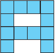
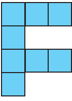
Question 2. Imagine $8$ identical cubes, glued together along faces to form the letter ‘ Letter C ’.
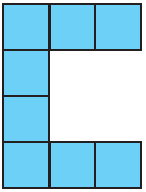
(i) This looks like a ‘ Letter C ’ from the front. What does it look like from the side? From the top?

(ii) Glue additional cubes to make a shape that looks like ‘ Letter C ’ from the front and ‘ Letter A ’ from the top.

(iii) Now, can you glue even more cubes to make it look like ‘ Letter C ’ from the front, ‘ Letter A ’ from the top, and ‘ Letter F ’ from the side?

(iv) Can you think of other letter combinations to make with a single combination of cubes in this manner?

Answer:

Given:

A set of 8 identical cubes arranged to form the letter ‘C’ as seen from the front. We are also given the shapes of letters ‘A’ and ‘F’ for subsequent parts of the problem.


(i) To Find: Side View and Top View of the letter ‘C’

Solution:

The letter ‘C’ as shown is made of a single layer of cubes. Let us assume the side of each cube is $a$ units.

1. Side View: When looking from the side (left or right), we only see the vertical profile of the cubes. Since the "backbone" of the 'C' consists of 4 cubes stacked vertically, the side view will appear as a vertical column of 4 squares.

2. Top View: When looking from the top, we see the width of the top horizontal arm. Since the top arm consists of 3 cubes (including the corner one), the top view will appear as a horizontal row of 3 squares.


(ii) To Find: A shape with Front View ‘C’ and Top View ‘A’

Solution:

To create a solid that looks like ‘C’ from the front and ‘A’ from the top, we must "extrude" the 'C' shape into three dimensions. We place cubes in a 3D grid such that:

$\text{Front Projection} = \text{Shape 'C'}$

$\text{Top Projection} = \text{Shape 'A'}$

This is done by placing a cube at coordinate $(x, y, z)$ only if the position $(x, z)$ belongs to the 2D letter 'C' and the position $(x, y)$ belongs to the 2D letter 'A'. This would require a much larger number of cubes to fill the intersection of these two "cylindrical" projections.


(iii) To Find: A shape with Front View ‘C’, Top View ‘A’, and Side View ‘F’

Solution:

Yes, this is mathematically possible using a technique called Voxel Intersection. A cube will exist at a position $(x, y, z)$ in a 3D grid if and only if:

1. The point $(x, z)$ is a part of the letter 'C' (Front View).

2. The point $(x, y)$ is a part of the letter 'A' (Top View).

3. The point $(y, z)$ is a part of the letter 'F' (Side View).

By checking every possible cube position in a bounding box (e.g., $4 \times 4 \times 4$), we can glue cubes only at the valid intersections. This results in a complex 3D solid that displays a different letter from each of the three primary directions.


(iv) Other Letter Combinations

Solution:

From an Indian perspective of engineering and design, this is a common exercise in spatial reasoning. Some other interesting combinations include:

1. H - I - L: A shape that looks like ‘H’ from the front, ‘I’ from the top, and ‘L’ from the side.

2. E - F - T: A shape that looks like ‘E’ from the front, ‘F’ from the top, and ‘T’ from the side.

3. X - Y - Z: These are more difficult but possible with higher resolution (more cubes).


Final Conclusion:

The views of an object are independent projections. By carefully arranging identical cubes in a 3D space, we can create objects that reveal entirely different shapes (like letters) when viewed from the Front, Top, and Side.

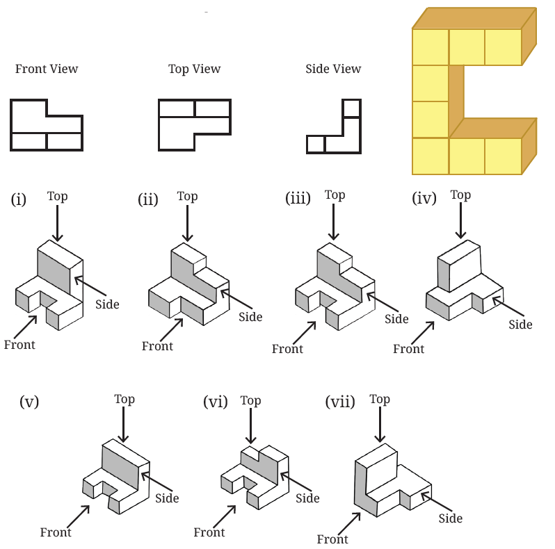
Question 3. Which solid corresponds to the given top view, front view, and side view?
Matchings solids (i through vii) with their respective Front, Top, and Side view projections

Answer:

Given:

We are given three 2D orthographic projections of a solid:

1. Front View: A step-like shape with a width of 2 units and a height of 2 units on the left side.

2. Top View: A $2 \times 2$ square area with the bottom-right corner missing (total of 3 squares visible).

3. Side View: An ‘L’ shape with a height of 2 units and a base width of 2 units.

We are also given seven 3D solids labeled (i) to (vii) made of identical cubes.


To Find:

Identify which of the seven solids corresponds exactly to the given set of projections.


Solution:

Let us analyze the projections and match them with the 3D structures:

1. Analysis of the Front View:

Looking at the Front arrow for each solid, the view must show 2 squares at the base and 1 square on the top-left corner. Solids (i), (iii), (iv), and (vi) satisfy this condition. Solid (vii) has a height of 2 on the right, so it is incorrect.

2. Analysis of the Side View:

Looking from the Side arrow, the view must be an ‘L’ shape (a vertical column of 2 and a horizontal square at the bottom). In solid (iv), the side view is just a vertical rectangle of $2 \times 1$. In solid (vi), the side view shows a notch. Solid (iii) perfectly matches the ‘L’ shape side view.

3. Analysis of the Top View:

Looking from the Top arrow, we must see 3 squares arranged in a $2 \times 2$ grid where one corner is empty. In solid (iii), we see one square at the back-left, one at the back-right, and one at the front-left. The front-right corner is empty. This matches the provided top view projection exactly.


Final Conclusion:

By comparing all three projections, we find that Solid (iii) is the only one that matches the Front, Top, and Side views provided.

$\text{Required Solid} = \text{Solid (iii)}$


Indian Perspective:

In the Indian curriculum for Class 8 Mathematics and Engineering Drawing, identifying solids from their 2D projections is a key skill for understanding Spatial Visualization. This exercise helps students translate 2D blueprints into 3D mental models, which is the basis for architecture and mechanical design.

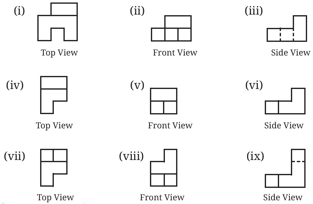
Question 4. Using identical cubes, make a solid that gives the following projections.
Grid showing nine sets of Top, Front, and Side view projections labeled i to ix

Answer:

Given:

Figure 11 shows three sets of projections (Top, Front, and Side views) labeled from (i) to (ix).


To Find:

Describe the construction of solids using identical cubes that match these projections.


Solution:

We analyze the projections to determine the arrangement of cubes for each of the three solids:

Solid 1 (Projections i, ii, iii):

1. Base Layer: Arrange 5 cubes on the floor. Looking at the Top View (i), place them in a $3 \times 2$ area, leaving the middle-front space empty.

2. Second Layer: Looking at the Front View (ii), place 2 cubes on top of the outer cubes of the back row.

3. Third Layer: Looking at the Side View (iii), place 1 cube on the very top of the back-right corner to achieve a height of 3 units.

Solid 2 (Projections iv, v, vi):

1. Base Layer: Looking at Top View (iv), arrange 4 cubes in an 'L' shape (3 in a row, with 1 extra attached at the end).

2. Second Layer: Looking at Front View (v), place 2 cubes on top of the front-most row to form a $2 \times 2$ square face.

3. Side View (vi): This arrangement naturally forms the 'L' shape seen from the side.

Solid 3 (Projections vii, viii, ix):

1. Base Layer: Similar to the previous solid, but the Top View (vii) indicates a partition, suggesting a $2 \times 2$ base with an extra cube.

2. Height: The Front View (viii) and Side View (ix) show a height of 3 units at the corner. Place cubes vertically at the corner to match this height.


Conclusion:

By following the Top View for the floor plan and the Front/Side Views for the height of each column, we can successfully construct the 3D solids from these 2D drawings.

Question 5. Find the number of cubes in this stack of identical cubes.
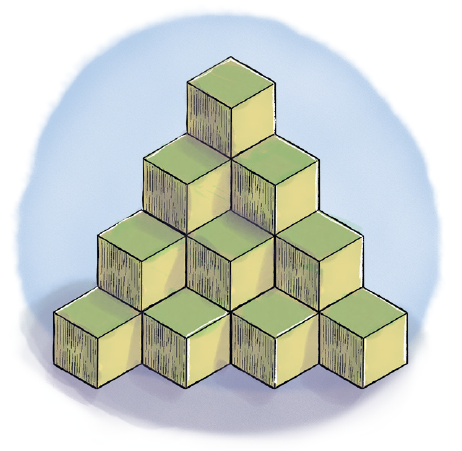
A complex 3D stack of identical cubes

Answer:

Given:

A stack of identical cubes arranged in a triangular pyramid-like structure (Fig. 12).


To Find:

The total number of cubes in the stack.


Solution:

To find the total number of cubes, we can count them layer by layer from the top to the bottom. Each layer forms a triangular arrangement.

1. Layer 1 (Top-most): There is only 1 cube at the very top.

$\text{Cubes in Layer 1} = 1$

2. Layer 2: Below the top cube, there are 3 cubes (arranged as $1 + 2$).

$\text{Cubes in Layer 2} = 3$

3. Layer 3: Below the second layer, there are 6 cubes (arranged as $1 + 2 + 3$).

$\text{Cubes in Layer 3} = 6$

4. Layer 4 (Bottom-most): The base layer has 10 cubes (arranged as $1 + 2 + 3 + 4$).

$\text{Cubes in Layer 4} = 10$

Now, we calculate the total number of cubes by adding all the layers together:

$\text{Total Cubes} = 1 + 3 + 6 + 10$

$\text{Total Cubes} = 20$


Final Answer:

The total number of cubes in the stack is 20.

Question 6. What are the different shapes the projection of a cube can make under different orientations?

Answer:

Given:

A 3D solid cube.


To Find:

The different 2D shapes that can be formed by the projection of a cube under different orientations.


Solution:

When a cube is projected onto a 2D plane (like a piece of paper or a screen), the resulting shape depends on the angle at which we view it:

1. Square: This occurs when one face of the cube is perfectly parallel to the plane of projection. Only one face is visible.

2. Rectangle: This occurs when the cube is tilted such that two opposite edges are parallel to the plane, but the faces are at an angle. It looks like a wider or narrower rectangle.

3. Hexagon: In Isometric Projection (a common technique in Indian engineering drawing), the cube is tilted so that its main diagonal is perpendicular to the plane. The resulting 2D outline is a regular hexagon.

4. Irregular Quadrilateral: If the cube is tilted at an arbitrary angle where no edges are parallel to the plane, the projection can be an irregular four-sided or six-sided polygon.


Final Conclusion:

The most common shapes formed by the projection of a cube are a Square, a Rectangle, and a Hexagon.


Figure It Out (Page No. 100 - 102)

Question 1. In addition to the $5$ ways shown in Fig. $4.8$, are there any additional ways of gluing $4$ cubes together along faces? Can you visualise and draw these as well?
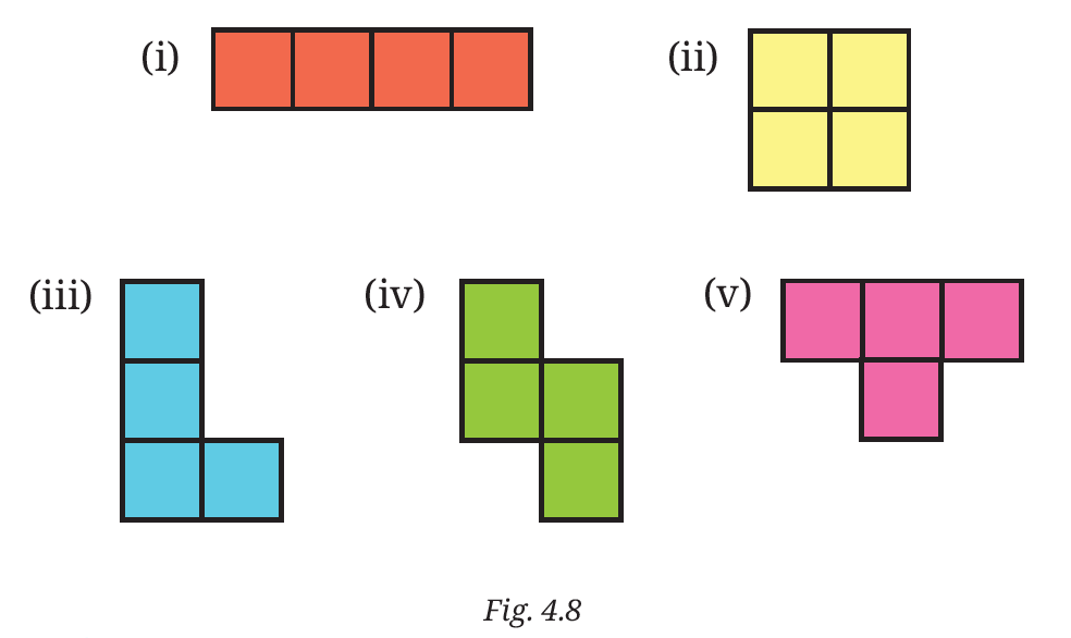
Ways of gluing four cubes together

Answer:

Given:

Figure 4.8 shows 5 ways of gluing 4 cubes together in a single plane (planar arrangements). These are known as tetrominoes in geometry.


To Find:

Whether there are additional ways of gluing 4 cubes together and visualizing them.


Solution:

In 2D (planar) geometry, there are only these 5 unique ways (I, O, L, Z, and T shapes). However, if we consider 3D space (where cubes can be glued in different layers or "twisted" into the third dimension), there are 3 additional ways to glue 4 cubes together. These are called non-planar polycubes.

The additional 3D arrangements are:

1. The Right-Hand Screw: Formed by taking a 'Z' shape and folding one end cube $90^\circ$ upwards into the third dimension.

2. The Left-Hand Screw: The mirror image of the right-hand screw.

3. The Branching/Tripod Shape: Formed by taking three cubes in an 'L' shape and gluing the 4th cube on top of the "corner" cube.

The total volume of any such arrangement, where $s$ is the side of one cube, remains constant:

$V = 4s^3$

(Total Volume of 4 cubes)


Final Conclusion:

Yes, if we move beyond 2D arrangements into 3D space, there are 3 more ways to glue 4 cubes, making a total of 8 unique 3D polycubes of order 4. In the Indian mathematical context, exploring these shapes is essential for understanding spatial symmetry and 3D visualization used in architecture and design.

Question 2. Draw the following figures on the isometric grid.

[Hint: It may be useful to determine whether the edge to be currently drawn — say, along the height — goes from down to up or up to down. Accordingly, draw the line segment on the grid either in the direction of the height axis or opposite to it.]
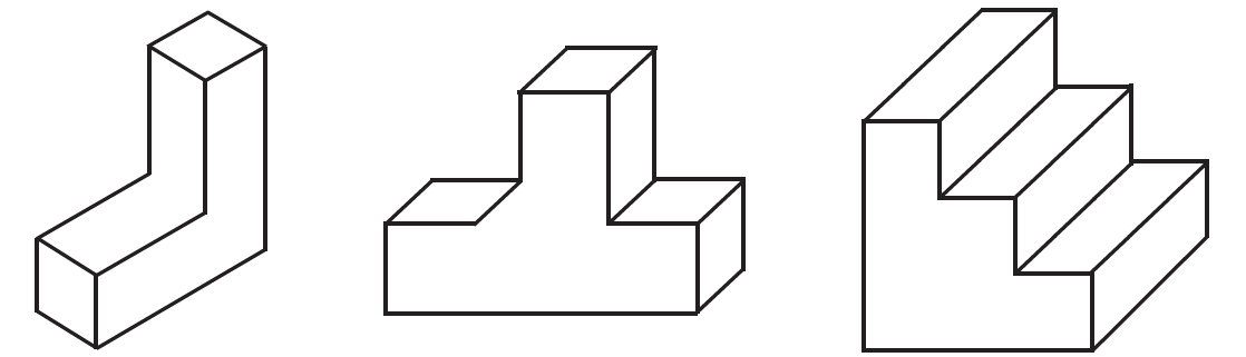
Figures for isometric grid drawing

Answer:

Given:

Three 3D figures: an L-shaped pillar, a T-shaped block, and a 3-step staircase.


To Find:

Represent these figures on an isometric grid.


Solution:

To draw these on an isometric grid, we follow the three principal axes: the vertical axis (height) and two horizontal axes at $30^\circ$ and $150^\circ$ (length and width).

1. L-Shaped Pillar:

Step 1: Draw a vertical line 3 units high for the back corner.

Step 2: Draw the base extending 1 unit to the left and 2 units to the right along the isometric lines.

Step 3: Complete the top surfaces by drawing parallel lines at each height level.

2. T-Shaped Block:

Step 1: Draw a horizontal base row of 3 units.

Step 2: From the center unit, draw a vertical column going 1 unit higher than the base.

Step 3: Connect all outer edges to show the depth (thickness) of 1 unit.

3. Three-Step Staircase:

Step 1: Start from the lowest step. Draw a $1 \times 1 \times 1$ cube.

Step 2: Adjacent to it, draw a $1 \times 1 \times 2$ (height) block for the second step.

Step 3: Behind that, draw a $1 \times 1 \times 3$ (height) block for the third step.

Step 4: Ensure all "treads" (top surfaces) and "risers" (vertical faces) are parallel to the respective grid axes.


Conclusion:

Using the isometric grid allows us to maintain the proportion of the cubes. Each edge of a cube is represented by one segment on the grid. In India, isometric drawing is a fundamental part of the Engineering Drawing and Applied Mathematics syllabus for Class 8 and above, as it provides a clear 3D representation without the distortion found in perspective drawings.

Question 3. Is there anything strange about the path of this ball? Recreate it on the isometric grid.

[Hint: Consider a portion of this figure that is physically realisable and identify the $3$ primary directions.]
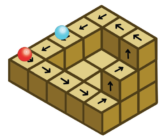
Path of the ball on isometric grid

Answer:

Analysis of the Ball's Path:

Yes, there is something very strange about the path. This is a classic optical illusion known as the "Penrose Stairs" or the "Impossible Staircase".

1. The Strangeness: By following the arrows, the ball appears to be continuously moving downwards from one cube to the next. However, after making four turns, the ball returns to the same starting position at the same apparent height. In real 3D space, if you are always descending, you must end up at a lower level than where you started.

2. Mathematical Impossibility: Let the height of one cube be $h$. In a closed loop, the total change in height must be zero:

$\sum \Delta h = 0$

(For any closed path)

In this figure, every step suggests a decrease in height ($-h$). For a loop of 12 visible steps:

$\text{Total Change} = 12 \times (-h) = -12h$

Since $-12h \neq 0$, this path is physically impossible.


Recreation on Isometric Grid:

To recreate this on an isometric grid, one must identify the three primary directions: Vertical (Height), $30^\circ$ to the right (Length), and $30^\circ$ to the left (Width). The illusion is created by drawing a line that should go "back" in depth as if it is going "down" in height, thus connecting two points that are actually at different elevations in a real 3D model.


Indian Perspective:

In Indian mathematics and art (similar to the works of M.C. Escher), such figures are used to study Spatial Paradoxes. They teach students that our brain interprets 2D drawings using 3D rules, and these rules can be "tricked" by clever geometry.

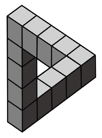
Question 4. Observe this triangle.

Impossible triangle illusion

(i) Would it be possible to build a model out of actual cubes? What are the front, top, and side profiles of this impossible triangle?

(ii) Recreate this on an isometric grid.

(iii) Why does the illusion work?

Answer:

(i) Physical Realisability and Profiles:

Building the Model: It is not possible to build a closed model of this triangle (known as the Penrose Triangle) out of actual cubes in real 3D space. If you try to build it, the ends of the three bars will never actually meet; there will always be a gap.

Profiles (Front, Top, and Side Views): If we consider the three bars that make up this shape, the projections would be:

1. Front View: Looks like an 'L' shape (one vertical bar and one horizontal bar meeting at a corner).

2. Top View: Looks like an 'L' shape or a straight bar, depending on the orientation of the third arm.

3. Side View: Looks like an 'L' shape.

The "triangle" shape is only visible from one specific viewing angle.


(ii) Recreation on Isometric Grid:

To draw this, you follow these steps on an isometric grid:

1. Draw a vertical column of 4 cubes.

2. From the bottom, draw a horizontal row of 4 cubes extending to the right.

3. From the top of the vertical column, draw a row of 4 cubes that appears to go "behind" and connect to the end of the horizontal row. On an isometric grid, this is done by aligning the edges such that the 2D drawing closes the loop, even though the 3D logic is broken.


(iii) Why the Illusion Works:

The illusion works because of Forced Perspective. Our brain is trained to interpret 2D lines on a page as depth in 3D space. The drawing uses parallelism and consistent shading to suggest that all three bars are perpendicular to each other. The "trick" happens at the corners where the 2D representation connects two points that are actually at different depths, but the brain ignores the depth inconsistency to maintain the "closed triangle" shape.


Conclusion:

The Penrose Triangle is a mathematical curiosity. It demonstrates that while 2D geometry can represent 3D objects, it can also represent objects that cannot exist in our three-dimensional world.