

| Classwise Concept with Examples | ||||||
|---|---|---|---|---|---|---|
| 6th | 7th | 8th | 9th | 10th | 11th | 12th |
| Content On This Page | ||
|---|---|---|
| Comparison of Line Segments | Measuring Line Segments | Measurement & Types of Angles |
| Perpendicular Lines | Types of Triangles | Types of Quadrilaterals |
| Three Dimensional Shapes | ||
Chapter 5 Understanding Elementary Shapes (Concepts)
Welcome to Chapter 5: Understanding Elementary Shapes! In our last chapter, we learned the basic language of geometry – points, lines, segments, angles, and circles. Now, we take the next exciting step! This chapter is all about looking closer at the shapes around us, learning how to measure them accurately, and understanding how we can group them based on their special characteristics. Think of yourselves as shape detectives! We will use tools like rulers and protractors to measure lengths and angles, and then use these measurements and our observation skills to classify different shapes, like triangles and quadrilaterals, into specific families. We will also begin exploring the world of three-dimensional shapes, the solid objects we encounter every day. This chapter builds directly on our basic geometrical ideas, adding the crucial skills of measurement and classification, which are essential for understanding geometry more deeply and applying it in real life.
Our first task is to get better at measuring. We know what a line segment is, but how long is it? We'll explore different ways to compare and measure line segments accurately using tools like a ruler and a divider. Then, we move on to angles. An angle measures the amount of 'turn' between two rays meeting at a point. We will learn that the standard unit for measuring angles is degrees ($^\circ$), and the instrument used is called a protractor. Understanding key angle measures is vital: a full turn or revolution is $360^\circ$, a half turn (forming a straight line) is a straight angle ($180^\circ$), and a quarter turn is a right angle ($90^\circ$). We will practice identifying and measuring these important angles.
Knowing how to measure angles allows us to classify them. We will learn the specific names for angles based on their size:
- An acute angle is smaller than a right angle (less than $90^\circ$).
- An obtuse angle is larger than a right angle but smaller than a straight angle (between $90^\circ$ and $180^\circ$).
- A reflex angle is larger than a straight angle (greater than $180^\circ$).
Next, we apply our measurement and observation skills to classify triangles, which are three-sided polygons. Triangles can be classified in two main ways:
- Based on their sides: An equilateral triangle has all three sides equal in length. An isosceles triangle has two sides of equal length. A scalene triangle has all three sides of different lengths.
- Based on their angles: An acute-angled triangle has all three angles acute. A right-angled triangle has one right angle. An obtuse-angled triangle has one obtuse angle.
We then extend our classification skills to quadrilaterals (four-sided polygons). There are many special types of quadrilaterals, and we will learn to identify them based on their properties related to sides (lengths, parallel pairs) and angles (right angles, equal angles). We will explore shapes like parallelograms, rectangles, squares, rhombuses, and trapeziums, understanding what makes each unique. We will also reinforce how to name other polygons based on their number of sides, such as pentagons (5 sides), hexagons (6 sides), and octagons (8 sides).
Finally, we step into the third dimension! We move from flat shapes (2D) to three-dimensional shapes (solids). We will learn to recognize common solids like cubes, cuboids (like boxes), cylinders (like cans), cones (like ice cream cones), spheres (like balls), and pyramids. For these shapes, we will learn to identify their key parts: the flat surfaces called faces, the line segments where faces meet called edges, and the corners where edges meet called vertices. This introduction to 3D shapes builds our spatial visualization skills. Throughout this chapter, numerous diagrams and examples will help us connect the names of shapes with their visual appearance and defining properties, making geometry understandable and engaging.
Comparison of Line Segments
A line segment is a part of a line with two fixed endpoints. A key property of a line segment is its length. Comparing line segments means determining which of the two segments is longer, shorter, or if they are of equal length. There are several methods to do this.
1. Comparison by Observation
This is the simplest method where we just look at two line segments and make a visual judgment about their lengths. If the difference in length is significant, our eyes can easily tell which one is longer.

In the figure above, by simple observation, we can say that the line segment $\overline{CD}$ is longer than the line segment $\overline{AB}$.
Limitation: This method is unreliable when the difference in lengths is very small. It is not precise and can lead to incorrect conclusions.
2. Comparison by Tracing
This method offers better accuracy than simple observation. To compare two line segments, say $\overline{AB}$ and $\overline{CD}$, we can use a sheet of tracing paper.
- Place the tracing paper over the line segment $\overline{AB}$.
- Carefully trace the line segment $\overline{AB}$ onto the paper.
- Move the tracing paper and place the traced segment over the line segment $\overline{CD}$ such that the traced point A falls on point C.
- Now, observe the position of the traced point B.
- If B falls exactly on D, then $\overline{AB}$ and $\overline{CD}$ are of equal length.
- If B falls between C and D, then $\overline{AB}$ is shorter than $\overline{CD}$.
- If B falls beyond D, then $\overline{AB}$ is longer than $\overline{CD}$.

Limitation: This method is more accurate than observation, but the process can be cumbersome, and slight inaccuracies can occur during tracing and positioning.
3. Comparison using a Ruler and a Divider
This is the most accurate and practical method for comparing line segments. It involves using geometric instruments.
Using a Ruler
A ruler is marked with units like centimetres (cm) and millimetres (mm). We can measure the length of each line segment and compare their numerical values.
- Place the ruler along the line segment $\overline{AB}$ such that the zero mark of the ruler coincides with point A.
- Read the mark on the ruler that coincides with point B. This gives the length of $\overline{AB}$.
- Repeat the process for the line segment $\overline{CD}$.
- Compare the two measured lengths. For instance, if AB = 4.5 cm and CD = 5.2 cm, we can conclude that $\overline{CD}$ is longer than $\overline{AB}$.

Using a Divider
A divider is an instrument with two pointed arms. It is used to compare lengths with high accuracy, as it avoids reading errors associated with ruler thickness or eye positioning.
- Open the divider and place its two pointed ends exactly on the endpoints A and B of the line segment $\overline{AB}$.
- Without changing the opening of the divider, lift it and place one end on point C of the line segment $\overline{CD}$.
- Observe where the other end of the divider falls.
- If it falls exactly on D, the line segments are equal. $(\overline{AB} = \overline{CD})$
- If it falls before D (between C and D), then $\overline{AB}$ is shorter than $\overline{CD}$. $(\overline{AB} < \overline{CD})$
- If it falls beyond D, then $\overline{AB}$ is longer than $\overline{CD}$. $(\overline{AB} > \overline{CD})$

This method is considered the most accurate for direct comparison as it involves no measurement reading, only direct transfer of length.
Measuring Line Segments
While comparison tells us if a line segment is longer, shorter, or equal to another, measurement assigns a specific numerical value to its length. The length is a measure of the distance between its two endpoints. The standard unit of length in the metric system is the metre (m), but for geometry on paper, we commonly use centimetres (cm) and millimetres (mm).
$1 \text{ cm} = 10 \text{ mm}$
Using a Ruler to Measure
A ruler is the most common instrument for measuring the length of a line segment. To ensure accuracy, it should be used correctly.
Correct Method of Measurement
- Take a ruler and place it along the line segment $\overline{AB}$.
- Align the ruler such that the zero mark ('0') on the ruler is exactly at one endpoint, say A.
- Keep your eye directly above the other endpoint, B, to avoid parallax error.
- Read the marking on the ruler that coincides with the endpoint B. This reading gives the length of the line segment $\overline{AB}$.

In the figure, the length of $\overline{AB}$ is 5.6 cm.
Potential Errors in Measurement
Several errors can occur while measuring with a ruler, leading to inaccurate results.
1. Incorrect Positioning of the Ruler
The edge of the ruler must be placed exactly along the line segment. If it is placed at an angle, the reading will be incorrect and longer than the actual length.
2. Parallax Error (Incorrect Eye Position)
The position of your eye while taking the reading is very important. Your eye must be positioned vertically right above the marking you are reading. If viewed from the side, the reading will appear shifted, which is known as a parallax error.
3. Error due to Worn-out '0' Mark
Sometimes, the ends of a ruler are broken, or the zero mark is not clearly visible. In such cases, you can use another full centimetre mark as the starting point.
For example, you can align endpoint A with the 1 cm mark on the ruler. If endpoint B corresponds to the 6.8 cm mark, then the length of $\overline{AB}$ is not 6.8 cm. You must subtract the starting mark from the final mark.
Length of $\overline{AB} = (\text{Final Reading}) - (\text{Initial Reading})$
Length of $\overline{AB} = 6.8 \text{ cm} - 1.0 \text{ cm} = 5.8 \text{ cm}$
4. Error due to Ruler Thickness
If the ruler is thick, the markings may not be very close to the paper. This can make it difficult to read the exact measurement and can contribute to parallax error. Using a thin ruler with sharp markings is always better.
Measurement & Types of Angles
An angle is formed by two rays sharing a common endpoint called the vertex. The measure of an angle corresponds to the amount of rotation required to move one arm to the position of the other arm around the vertex.
Measurement of Angles
Unit of Measurement
The standard unit for measuring an angle is the degree, denoted by the symbol $^\circ$. A complete rotation or a full circle is divided into 360 equal parts, where each part is one degree ($1^\circ$).
- A complete turn = $360^\circ$
- A half turn (a straight line) = $\frac{1}{2} \times 360^\circ = 180^\circ$
- A quarter turn (a right angle) = $\frac{1}{4} \times 360^\circ = 90^\circ$
Using a Protractor
A protractor is a geometric instrument used to measure and draw angles. It is usually a semi-circular device with degree markings from $0^\circ$ to $180^\circ$ on two scales (an inner scale and an outer scale).

Steps to Measure an Angle (e.g., $\angle ABC$):
- Place the protractor on the angle so that the midpoint (or center) of the protractor is exactly on the vertex B of the angle.
- Adjust the protractor so that the baseline (the $0^\circ$ line) aligns perfectly with one arm of the angle, say $\overrightarrow{BC}$.
- Look at the scale that starts with $0^\circ$ along the arm $\overrightarrow{BC}$. Read the degree marking on this scale where the other arm, $\overrightarrow{BA}$, crosses the protractor.
- This reading is the measure of the angle in degrees.

Types of Angles (Based on Measurement)
Angles are classified into different types based on their degree measure.
| Type of Angle | Description | Measure | Figure |
|---|---|---|---|
| Zero Angle | The two arms of the angle overlap completely. There is no rotation. | $0^\circ$ | 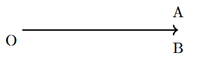 |
| Acute Angle | An angle that is smaller than a right angle. | Greater than $0^\circ$ and less than $90^\circ$ | 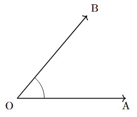 |
| Right Angle | An angle that forms a perfect corner, like that of a square. It is one-quarter of a full turn. | Exactly $90^\circ$ | 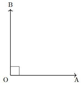 |
| Obtuse Angle | An angle that is larger than a right angle but smaller than a straight angle. | Greater than $90^\circ$ and less than $180^\circ$ | 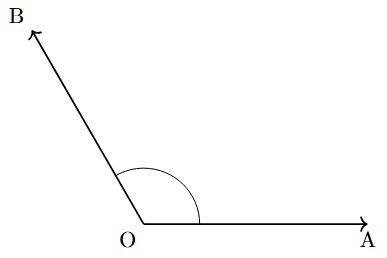 |
| Straight Angle | An angle that forms a straight line. It is one-half of a full turn. | Exactly $180^\circ$ | 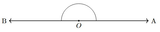 |
| Reflex Angle | An angle that is larger than a straight angle but smaller than a complete angle. It represents the larger turn between two arms. | Greater than $180^\circ$ and less than $360^\circ$ | 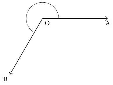 |
| Complete Angle | An angle where one arm has made a full rotation to return to its starting position. | Exactly $360^\circ$ | 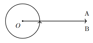 |
Perpendicular Lines
In geometry, the orientation of lines relative to each other is a key concept. We have already seen parallel lines (which never meet) and intersecting lines (which meet at a point). Perpendicular lines are a special case of intersecting lines.
Definition of Perpendicular Lines
Two lines, rays, or line segments are said to be perpendicular to each other if they intersect at a right angle (i.e., at an angle of exactly $90^\circ$).

In the figure above, line $l$ intersects line $m$ at a right angle. Therefore, they are perpendicular to each other.
Notation: The symbol for "is perpendicular to" is $\perp$. So, we can write $l \perp m$. This is read as "line $l$ is perpendicular to line $m$".
Real-life examples include the adjacent edges of a book, the corner of a wall, and the letter 'T'.
Perpendicular Bisector
The term "perpendicular bisector" describes a special line that has two distinct properties related to a given line segment.
A perpendicular bisector of a line segment is a line (or ray or segment) that divides the given line segment into two equal parts at a right angle.
For a line $l$ to be a perpendicular bisector of a line segment $\overline{AB}$, it must satisfy two conditions:
- It must be perpendicular to $\overline{AB}$. ($l \perp \overline{AB}$)
- It must pass through the midpoint of $\overline{AB}$. (It must bisect $\overline{AB}$, meaning it divides it into two equal segments).

In the figure, line $l$ intersects segment $\overline{AB}$ at point M.
- The angle of intersection is $90^\circ$, so $l \perp \overline{AB}$.
- Point M is the midpoint of $\overline{AB}$, so $AM = MB$.
Types of Triangles
A triangle is a polygon with three sides, three vertices, and three angles. They are one of the most fundamental shapes in geometry. Triangles can be classified into different types based on the length of their sides or the measure of their angles.
Classification of Triangles Based on Sides
This classification depends on the relationship between the lengths of the three sides of the triangle.
1. Equilateral Triangle
A triangle in which all three sides have the same length is called an equilateral triangle. Because all sides are equal, all three interior angles are also equal, with each measuring $60^\circ$. An equilateral triangle is a regular polygon.
In $\triangle ABC$, if $AB = BC = CA$, then it is an equilateral triangle.

2. Isosceles Triangle
A triangle in which any two sides have the same length is called an isosceles triangle. The angles opposite the equal sides are also equal in measure.
In $\triangle PQR$, if $PQ = PR$, then it is an isosceles triangle. Consequently, $\angle Q = \angle R$.

3. Scalene Triangle
A triangle in which all three sides have different lengths is called a scalene triangle. As a result, all three of its interior angles also have different measures.
In $\triangle XYZ$, if $XY \neq YZ \neq ZX$, then it is a scalene triangle.

Classification of Triangles Based on Angles
This classification depends on the measure of the interior angles of the triangle. The sum of angles in any triangle is always $180^\circ$.
1. Acute-angled Triangle
A triangle in which all three interior angles are acute (i.e., each angle is less than $90^\circ$) is called an acute-angled triangle.

2. Right-angled Triangle
A triangle in which one of the interior angles is a right angle (exactly $90^\circ$) is called a right-angled triangle. The side opposite the right angle is the longest side and is called the hypotenuse. The other two angles are always acute.

3. Obtuse-angled Triangle
A triangle in which one of the interior angles is an obtuse angle (i.e., greater than $90^\circ$ but less than $180^\circ$) is called an obtuse-angled triangle. A triangle can have only one obtuse angle.

Types of Quadrilaterals
A quadrilateral is a polygon with four sides, four vertices, and four angles. The sum of the interior angles of any convex quadrilateral is $360^\circ$. The family of quadrilaterals includes several special types with unique properties.

1. Trapezium (Trapezoid)
A trapezium is a quadrilateral with at least one pair of parallel sides. The parallel sides are called the bases, and the non-parallel sides are called the legs.
- An Isosceles Trapezium is a special case where the non-parallel sides (legs) are equal in length.

2. Parallelogram
A parallelogram is a quadrilateral with two pairs of parallel sides. It has several important properties:
- Opposite sides are parallel ($AB \parallel DC$ and $AD \parallel BC$).
- Opposite sides are equal in length ($AB = DC$ and $AD = BC$).
- Opposite angles are equal ($\angle A = \angle C$ and $\angle B = \angle D$).
- The diagonals bisect each other (they cut each other into two equal halves).

3. Rhombus
A rhombus is a special type of parallelogram in which all four sides are of equal length. It has all the properties of a parallelogram, plus:
- All four sides are equal ($AB = BC = CD = DA$).
- The diagonals are perpendicular bisectors of each other (they intersect at $90^\circ$ and bisect each other).

4. Rectangle
A rectangle is a special type of parallelogram in which all four angles are right angles ($90^\circ$). It has all the properties of a parallelogram, plus:
- All angles are equal to $90^\circ$.
- The diagonals are equal in length.

5. Square
A square is a special rectangle with all four sides of equal length. It is also a special rhombus with four right angles. A square is a regular quadrilateral and possesses the properties of a parallelogram, a rectangle, AND a rhombus.
- All four sides are equal.
- All four angles are $90^\circ$.
- Diagonals are equal in length.
- Diagonals are perpendicular bisectors of each other.

6. Kite
A kite is a quadrilateral that has two distinct pairs of equal-length adjacent sides. It is not a parallelogram.
- Two pairs of adjacent sides are equal ($AB = AD$ and $CB = CD$).
- One pair of opposite angles are equal ($\angle B = \angle D$).
- One of the diagonals is the perpendicular bisector of the other.

Three Dimensional Shapes
So far, we have discussed shapes that can be drawn on a flat surface like paper. These are called two-dimensional (2D) or plane shapes. They have only two dimensions: length and width. Shapes that exist in the real world have three dimensions: length, width, and height (or depth). These are called three-dimensional (3D) shapes or solid shapes.
Components of 3D Shapes
Most 3D shapes (polyhedra) are described by their faces, edges, and vertices.
- Face: A face is a flat surface of a 3D shape. For example, a cube has 6 square faces.
- Edge: An edge is a line segment where two faces meet. A cube has 12 edges.
- Vertex: A vertex is a point or corner where three or more edges meet. A cube has 8 vertices. (Plural: vertices).
For any convex polyhedron, the relationship between the number of faces (F), vertices (V), and edges (E) is given by Euler's Formula:
$$F + V - E = 2$$
Common 3D Shapes
Three-dimensional shapes are solids that have length, width, and height. They can be broadly categorized into two groups: polyhedra, which have flat polygonal faces, and non-polyhedra, which have curved surfaces.
Polyhedra (Shapes with Flat Faces)
A polyhedron is a 3D shape whose surfaces are all flat polygons. They are defined by their faces, edges, and vertices.
Cube

A cube is a special type of cuboid where all six faces are identical, congruent squares. It is one of the five Platonic solids and is also known as a regular hexahedron. All its angles are right angles. Examples include a standard die, a sugar cube, or a Rubik's Cube.
- Faces (F): 6
- Vertices (V): 8
- Edges (E): 12
Cuboid

A cuboid, or rectangular prism, is a convex polyhedron with six rectangular faces. All its angles are right angles, and its opposite faces are identical. It is one of the most common shapes in the real world. Examples include a shoebox, a brick, a book, or a room.
- Faces (F): 6
- Vertices (V): 8
- Edges (E): 12
Prisms
A prism is a polyhedron composed of two parallel, congruent polygonal bases and a set of lateral faces that are parallelograms, connecting the corresponding edges of the two bases.
Prisms are named after the shape of their base. They are further classified as right prisms (where the lateral faces are rectangles, perpendicular to the base) or oblique prisms (where the lateral faces are parallelograms and the prism appears slanted).
 vs. Oblique Prism (right)")
Common types include:
- Triangular Prism: Has two triangular bases and three rectangular sides. (Faces: 5, Vertices: 6, Edges: 9)
- Rectangular Prism (Cuboid): Has two rectangular bases and four rectangular sides. (Faces: 6, Vertices: 8, Edges: 12)


Pyramids
A pyramid is a polyhedron formed by connecting a single polygonal base to a point, called the apex. The faces formed by connecting each edge of the base to the apex are triangles, and these are known as the lateral faces.
Pyramids are named after the shape of their base. They are classified as right pyramids (where the apex is directly above the center of the base) or oblique pyramids (where the apex is off-center).
 vs. Oblique Pyramid (right)")
Common types include:
- Triangular Pyramid (Tetrahedron): Has a triangular base and three triangular sides. (Faces: 4, Vertices: 4, Edges: 6)
- Square Pyramid: Has a square base and four triangular sides. (Faces: 5, Vertices: 5, Edges: 8)


Non-Polyhedra (Shapes with Curved Surfaces)
These are 3D shapes that have at least one curved surface. They are not polyhedra because not all their faces are polygons.
Cylinder

A cylinder is a solid geometric figure with two parallel, identical circular bases and a single curved surface connecting them. It can be generated by rotating a rectangle around one of its sides. It has a uniform circular cross-section throughout its height. Examples include a food can, a pipe, a candle, or a log.
- Faces: 2 flat circular bases and 1 curved lateral surface.
- Edges: 2 circular edges where the curved surface meets the bases.
- Vertices: 0.
Cone

A cone is a solid with a single circular base that tapers to a single point called the apex or vertex. It can be generated by rotating a right-angled triangle around one of its perpendicular sides. The distance from the apex to any point on the circular edge of the base is the slant height. Examples include an ice cream cone, a party hat, or a traffic cone.
- Faces: 1 flat circular base and 1 curved lateral surface.
- Edges: 1 circular edge.
- Vertices: 1 (the apex).
Sphere

A sphere is a perfectly symmetrical and round 3D object. It is defined as the set of all points in three-dimensional space that are equidistant from a single central point. This fixed distance is the radius of the sphere. It has no edges or vertices. Examples include a ball, a marble, or a planet (approximately).
- Faces: 1 continuous curved surface.
- Edges: 0.
- Vertices: 0.
Common 3D Shapes
Polyhedra (Shapes with Flat Faces)
| Shape | Description | Faces (F) | Vertices (V) | Edges (E) | Figure |
|---|---|---|---|---|---|
| Cube | A solid with 6 identical square faces. | 6 | 8 | 12 |  |
| Cuboid | A solid with 6 rectangular faces. Also known as a rectangular prism. | 6 | 8 | 12 | 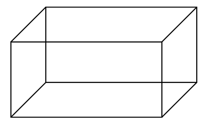 |
| Triangular Prism | A prism with two parallel triangular bases and three rectangular side faces. | 5 | 6 | 9 | 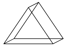 |
| Square Pyramid | A pyramid with a square base and four triangular faces that meet at an apex. | 5 | 5 | 8 | 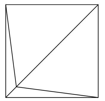 |
Non-Polyhedra (Shapes with Curved Surfaces)
| Shape | Description | Properties | Figure |
|---|---|---|---|
| Cylinder | A solid with two identical, parallel circular bases and one curved side. | 2 flat faces (circles), 1 curved face, 2 circular edges, 0 vertices. | 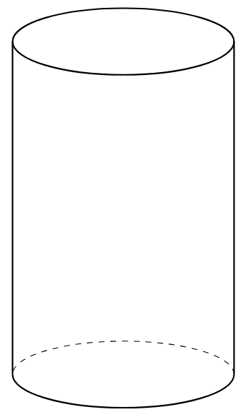 |
| Cone | A solid with one circular base and a curved surface that tapers to a single vertex (apex). | 1 flat face (circle), 1 curved face, 1 circular edge, 1 vertex. | 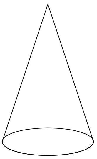 |
| Sphere | A perfectly round solid. Every point on its surface is equidistant from its center. | 1 curved face, 0 edges, 0 vertices. | 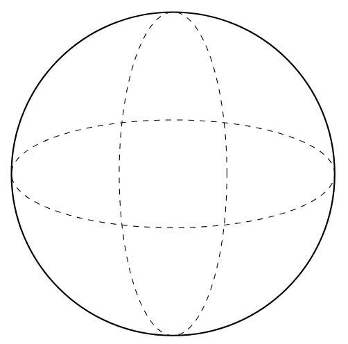 |